Pile Location Detection

Nondestructive pile location detection
Pile layout Detection

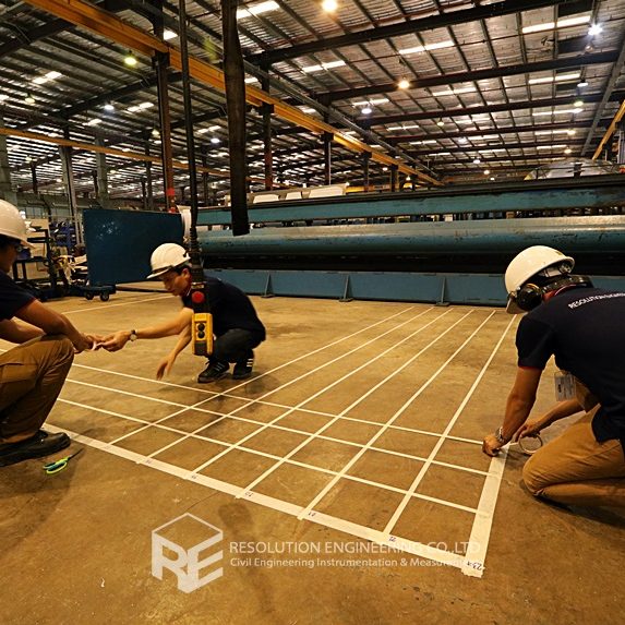
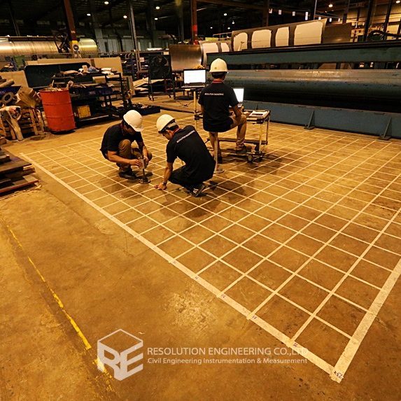
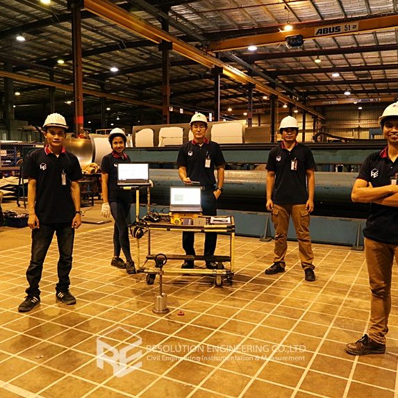
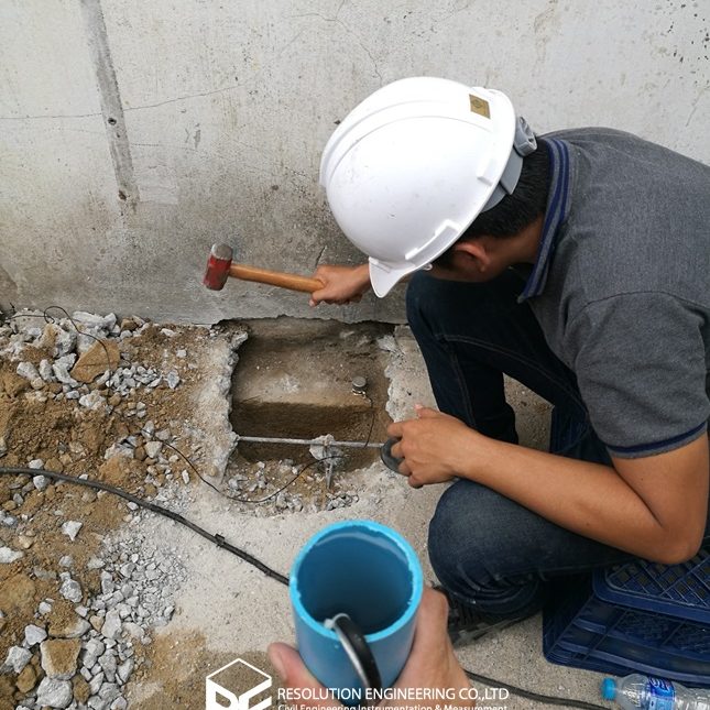
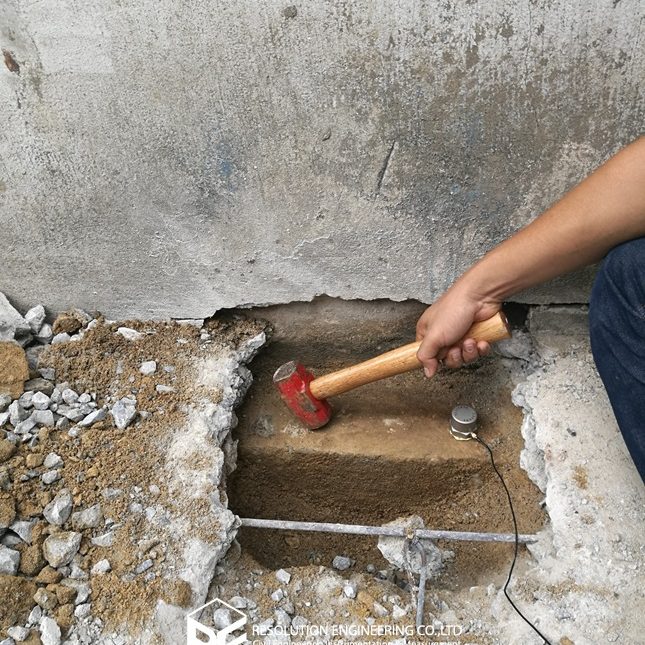
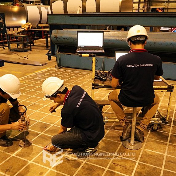
One very common problem is that the drawing or evidence of the floor pile layout or location is missing. As a result, a thorough floor capacity analysis cannot be done. Load carrying capacity also cannot be verified. When dealing with one of these cases, RE team conducted the Non-Destructive Pile Detection on the concrete floor of a factory in the Bangpa-In Industrial Estate. This factory was built a long time ago, and the pile location and layout no longer exist. By means of seismic waves generated from a drop hammer and received by accelerometers via a dynamic data logging system, the acceleration record was analyzed, and the pile location was determined.

Read article

RC pile integrity test

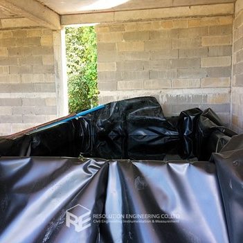
At a newly constructed school in Phuket, which consists of two building blocks, it was suspected that the strength of both the 1stfloor and the 2ndfloor precast slabs was not sufficient as it may have been shown in the design. Thus, a load test was requested to determine whether the structure was safe given the current load condition. Three slab panels were selected for the test. Panel 1 was located on the 1st floor of Building Block 2 while Panels 2 and 3 were on the 2ndfloor of Building Block 1. Water ponding was used as the applied load with the maximum of  560 kg/m2.

Read article

Parallel Seismic Test

The Parallel Seismic Test is a non-destructive test used to determine the pile length when the details of the foundation are no longer available, or when the constructed pile length is questionable. Test equipment consists of accelerometers, an impact hammer, and the data acquisition system (DAQ). The hammer is used to create an impact at connecting point between the structure, and the pile or the foundation (more effective with the direct impact at the top of the pile itself). At the point of impact, waves will firstly be detected by the accelerometer and displayed by DAQ. Next, the waves are transferred along the pile, and shear waves will be propagating through the soil to the receiver accelerometer in a PVC pipe located 1.5 m from the pile cap. The test is conducted at every 1m receiver intervals throughout the entire length of the PVC pipe.

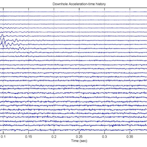
Any diffraction or change in slope that occurs in the data as a result of the pile tip acting as a point diffractor and a reflector indicates the end of the pile. Thus, the pile length can be determined.

Please find below a sample of the test results from a past project conducted by RE using the Parallel Seismic Test.

Read article

Ferro scan Test

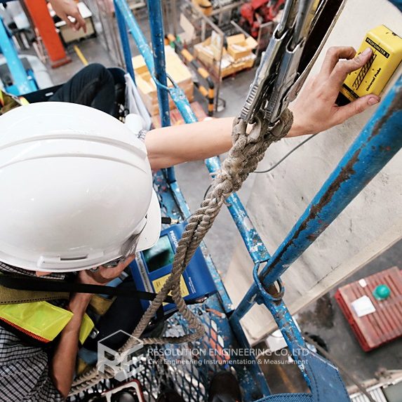
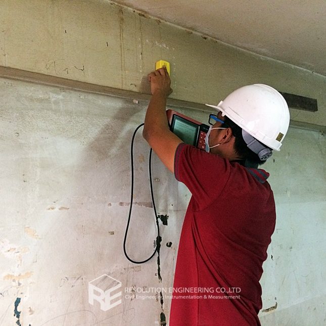
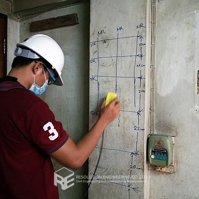
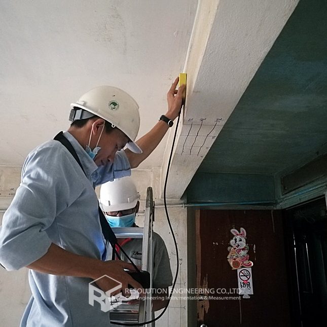
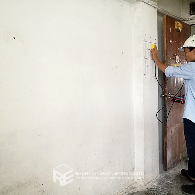
The Ferro Scan Test or Electromagnetic Cover Measurement is one of the non-destructive tests used to determine the positions and the quantity of reinforcement steel inside concrete members. This test can be used to inspect old buildings which do not have structural drawings or may only have outdated drawings which may not include any later renovations. The Ferro Scan Test can be used to determine the current positions and the quantity of reinforcement steel in concrete members, the data of which can be further used to determine the load carrying capacity of the structures.

The Ferro Scan Test operates on the principle of the electromagnetic field. The emitter head releases an electromagnetic field, and when the emitter head is placed closer to any reinforcement area, the reinforcement bar with induction properties will disturb the electromagnetic field. Thus, the area where the electromagnetic field is shown to be disturbed can represent the location of the reinforcement steel.

Read article